
Matching Coil Adjustment
There is a specific procedure which must be followed if proper adjustment of a shunt matching coil is to be achieved (read that as low SWR over a very wide range of frequencies), as required when using a remotely tuned antenna. In addition, the coil must be correctly configured. For example, long, skinny coils do not work as well as ones where the length and diameter are approximately the same. Further, for best results the coil should be installed as clear of surrounding sheet metal as possible. When matching coils are mounted close to mounting brackets, and vehicle sheet metal, their performance and linearity will suffer. Incidentally, his may require relocating factory-supplied coils.
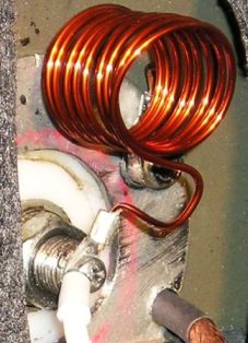
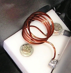
The coil at left has 9 turns, is 1 inch inside diameter, and wound with #14 Thermalese® (enameled) wire. The one on the right is 7 turns. You can also use building wire, but it’s a little harder to work with. In actual use, the turns are spaced a little further apart to adjust the inductance. The coil needs to be about 1 uH, but in the real world, the value may be between .5 uH and 1.5 uH depending on the actual input impedance at resonance.
Matching is achieved by borrowing a small amount of capacitive reactance from the antenna (when tuned slightly above the operating frequency), and the inductance of the coil. Together, they form a highpass, LC network which transforms the antenna’s low impedance (typically 25 ohms or so) to that of the 50 ohm feed line
Coil Adjustment
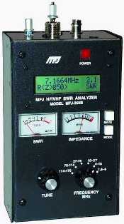
If you own an antenna analyser, you can adjust the turns spacing to provide a good compromised match (<1.5:1) across the operating range of the antenna. Once you’ve installed the coil, here’s the tuning method to use. By the way, this process is very difficult to accomplish with just an SWR bridge, but it can be done. It just takes about 10 times longer, and you have to actually transmit on the air to do so.
 Move the antenna to the 80 meter band. The actual frequency isn’t important. Adjust the frequency on the analyzer until the X=Ø, or as close to it as you can (the SWR reading is not important at this point). Read the R value. If it is less than 40 ohms, stretch out the coil slightly, and readjust the analyzer’s frequency so X=Ø once again. If the reading is lower than the first try, squeeze the coil together, and try again. Repeat the process until the R reading is about 40 ohms when X=Ø. This relates to an SWR of 1.25:1. Remember, the only time the SWR readout will be accurate (and significant), is when X=Ø, and R is close to 50 ohms.
Move the antenna to the 40 meter band (the actual frequency isn’t important), and adjust the analyzer’s frequency until X=Ø, and read the R value. In most cases, it will be about the same spot as it was on 80 meters. If it is not, it may be necessary to compromise between the two bands.
Once you’ve completed the 80 and 40 meter adjustments, move the antenna to the 20 meter band (the actual frequency isn’t important). Adjust the frequency on the analyzer until X=Ø, and read the R value. It will usually be closer to 50 ohms than either 80 or 40 meters. You can check the rest of the bands if you desire. Typically, they will read very close to the 20 meter R value.
If a compromise can’t be reached between 80 and 40, or the 20 meter R reading is far removed for 50 ohms when X=Ø, then chances are there is an inadequate ground plane under the antenna, or there is too much stray capacitance between the antenna and the body of the vehicle, or both!
End Notes
Here are a few pointers. First, the number of turns may vary from 7 to 10 turns. The actual number needed depends on a lot of factors including the size of wire, the overall length of the coil, its diameter, and whether it is insulated or not (building wire for example). The dimensions suggested (1 inch long, 1 inch in diameter, and 9 turns) will suffice most of the time, however.
An SWR bridge can be used to adjust the coil, but requires about 10 times the effort, and you have to transmit while you’re making the adjustments (not always advisable). Starting with the suggested dimensions (1 inch long, 1 inch in diameter, and 9 turns), find the lowest SWR on 80 meters (the actual frequency isn’t important). This should be done by adjusting the antenna’s resonant point. If it is under 1.5:1, move to 40 meters (the actual frequency isn’t important). If the lowest SWR is higher than the 80 meter point, squeeze or elongate the coil, and readjust the antenna to the lowest SWR. The lowest SWR point should be set half way between the 80 meter point, and the original 40 meter point. After each adjustment, you must once again find the lowest SWR by re-resonating the antenna. You will have to go back and forth several times between 80 and 40 to get the coil properly adjusted. Properly set, the SWR should be the same on 80 and 40, or as close to it as you can. It should be obvious that an antenna analyzer is a much better tool for adjusting the shunt matching coil.
If you do the coil adjustment correctly, you will be rewarded with a low SWR at any resonant point the antenna can be tuned to. The coil will not need further adjustment unless you change the antenna’s length, or add a cap hat, or perhaps relocate the antenna.
Lastly, you can use a shunt base coil to match any mobile antenna, even a monoband one. However, if you’re using a remotely tuned antenna, this matching method is the only one that doesn’t require any adjustments when switching between bands.